This a tutorial about how to build home automation system for switching lights.
Raspberry PI perfect home automation. It's small, always connected to the internet and has a full-blown Linux with a direct access to GPIO ports.
At first I looked at X10, but dismissed it because it's not that popular in Europe and quite expensive.
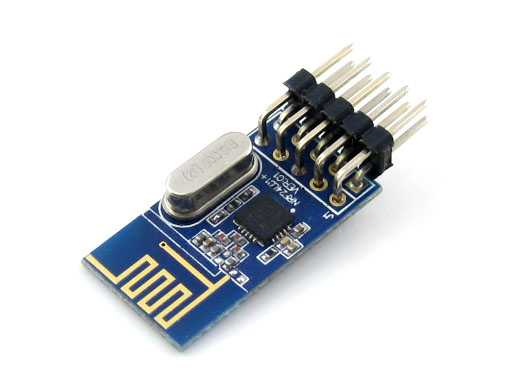
Then I found these bad boys:
nRF24L01+ is a tiny transceiver with SPI interface which operates on 2.4GHz frequency. It's an ISM band which means that you can use it without any certifications and permissions.
SPI interface means that it can be easily connected to Arduino as a receiver and Raspberry PI as the transmitter. I wont describe here how to connect nRFs to SPI interfaces because it's all over the internet already.
I used RF24 library which is available for Arduino and a Raspberry PI. I would recommend to try to compile one of the examples and establish communication between an Arduino and a Raspberry PI before going further.
Hardware
Receiver hardware consists of 3 parts - Atmega328P, 5v power adapter and a relay.
Atmega328p
I didn't want to use a full blown Arduino, so I just programmed an Atmega chip, made sure that it worked and then run in a standalone mode.
5v power supply
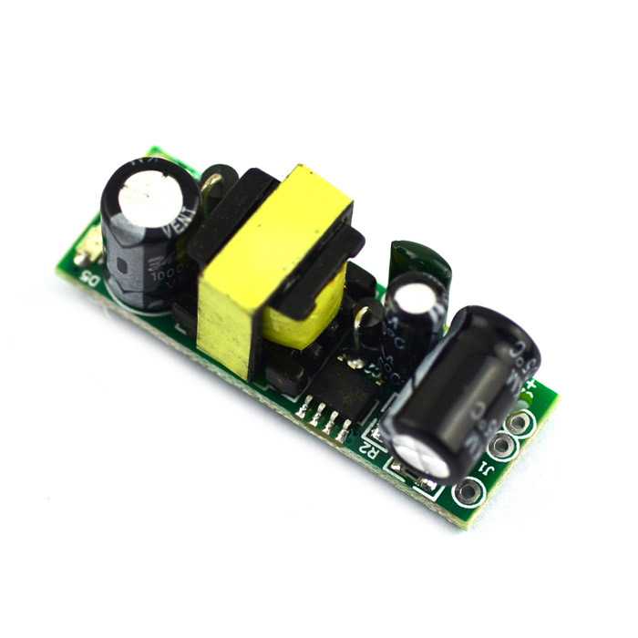
Power requirements of the whole thing are extremely small, so almost any 5v power supply would suffice. I bought this one from DealExtreme:
If you have phone chargers lying around they might also be a good option :)
Relay
I bought one of the 5v relays available from DealExtreme or any other similar site:
It operates under 5v, has a built-in transistor so it can be directly connected to an AVR chip and has a tiny led indicator.
Wiring
Receiver
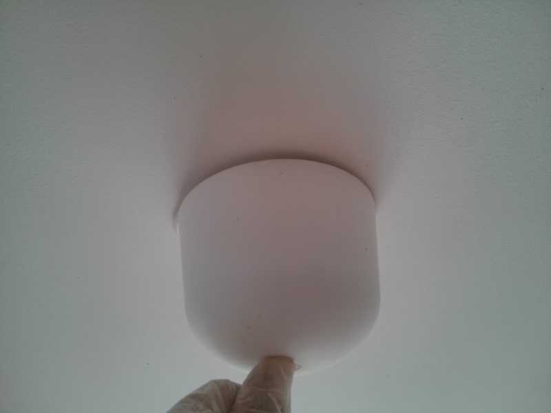
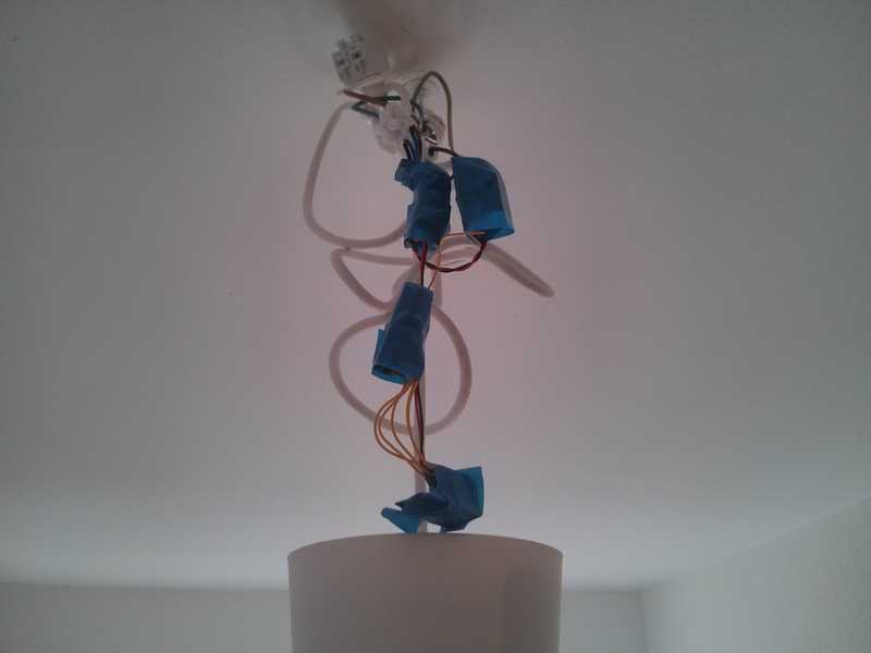 As you can see I didn't use any board for the build. The main reason for that is flexibility - this way I can easily bend it the way I want, so it can be placed neatly inside of most lamps:
Raspberry Pi hardware
On the Raspberry PI side all is pretty standard - it's connected to the Ethernet network and has nRF chip connected to it via SPI protocol.
Software
Receiver code
Code for the receiver is available here https://github.com/Leonti/sketchbook/blob/master/receiver/receiver.ino:
#include <SPI.h>
#include "nRF24L01.h"
#include "RF24.h"

#define RF_SETUP 0x17

// Set up nRF24L01 radio on SPI pin for CE, CSN
RF24 radio(8,9);

int relay = 4;

const uint64_t id = 0xF0F0F0F0E4LL;

void setup(void) {

  pinMode(relay, OUTPUT);
  digitalWrite(relay, HIGH);

  radio.begin();

  // Enable this seems to work better
  radio.enableDynamicPayloads();
  // RF24_1MBPS RF24_250KBPS
  radio.setDataRate(RF24_1MBPS);
  radio.setPALevel(RF24_PA_MAX);
  radio.setChannel(76);
  radio.setRetries(15,15);

  radio.openReadingPipe(1, id);

  radio.startListening();

  delay(1000);
}

void loop(void) {

  while(radio.available()) {
    uint8_t len = radio.getDynamicPayloadSize();
    char receivePayload[32];
    radio.read(receivePayload, len);
    receivePayload[len] = 0;

    if (!strcmp(receivePayload, "on")) {
      digitalWrite(relay, HIGH);
    } else {
      digitalWrite(relay, LOW);
    }
  }
}
The code is very straightforward - we initialize the transceiver and then react on incoming messages which could be either "on" or "off". If it's "on" we set the relay pin to HIGH status, so it turns the light on and we do the opposite when we receive "off" message.
Light is switched on every time the chip gets power. This way it still operates like a normal switch if needed.
Each chip has it's own id, which is hard-coded and changed before each reflash.
Transmitter code
Transmitter code is run on Raspberry PI and is available here https://github.com/Leonti/lights/blob/master/rf/onoff.cpp:
/*
 *
 *
 *  CE is connected to GPIO25
 *  CSN is connected to GPIO8
 *
 *  Refer to RPi docs for GPIO numbers
 *
 */

#include <cstdlib>
#include <iostream>
#include "RF24.h"

using namespace std;

// CE and CSN pins On header using GPIO numbering (not pin numbers)
RF24 radio("/dev/spidev0.0",8000000,25);  // Setup for GPIO 25 CSN

void send(uint64_t id, int on)
{
 //
 // Refer to RF24.h or nRF24L01 DS for settings
 radio.begin();
 radio.enableDynamicPayloads();
 radio.setAutoAck(1);
 radio.setRetries(15,15);
 radio.setDataRate(RF24_1MBPS);
 radio.setPALevel(RF24_PA_MAX);
 radio.setChannel(76);
 radio.setCRCLength(RF24_CRC_16);

 radio.stopListening();
 radio.openWritingPipe(id);

 usleep(1000);

 char sendPayload[32];

 if (on) {
  strcpy(sendPayload, "on");
 } else {
  strcpy(sendPayload, "off");
 }

 if(radio.write(sendPayload, 32)) {
  printf("OK\n");
 } else {
  printf("ERROR\n");
 }
}


int main(int argc, char** argv)
{

 if (argc > 2) {

        char *end;
        uint64_t id = strtoull(argv[1], &end, 16);

        int on = 0;
        if (!strcmp("on", argv[2])) {
            on = 1;
        }
  send(id, on);
 }
 return 0;
}
SPI has to be enabled on the Raspberry PI for this code to work.
It accepts command line arguments which as in case with the receiver can be "on" or "off" and sends commands to the receiver with id provided as the first argument.
If everything works you should be able to turn lights on/off by running
./onoff 0xF0F0F0F0E1LL onThe UI
Even though being able to switch lights in your apartment via command line is immensely cool it's not a very convenient solution. I wrote a small Node.js app with a simple UI which allows to switch the light via web browser. With a simple port forwarding I'm able to switch switch them from the Internet. I use dynamic dns to access the page at the same url. Here is the code for the server https://github.com/Leonti/lights.
Android app
Since it's a web app it can be accessed from a variety of clients.
Opening web browser each time you want to switch a light can be cumbersome, so I wrote a simple Android app with 8 buttons (on/off for 4 rooms) which sends the requests to the server + 2 buttons to turn everything off or on, very useful when going to sleep :)
With Android geolocation API it is very easy to listen to the events when a phone enters or exits a particular zone, which I used to turn lights off when I leave my apartment and turn them on when I'm back (of course it's only triggered after certain hour, so it's still a daytime lights stay off).
The source for the app is not released yet, because the address of my server is hard-coded in the app itself.
Lessons and improvements
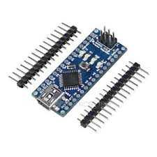
- Using Atmega328p directly was a good decision size- and cost-wise, but I have to take it out each time I want to reprogram it, which prevented me from improving the code over time. If I had to do it again I would choose Arduino Nano without the connectors:
It's only slightly bigger, but has an FTDI chip, so I could program it while it's still in operation.
- 5v power supplies are a bit noisy (they have a high-pitched sound), didn't bother me but might be annoying to some people.
- Switch state could be queried from the lights, but I didn't find it all that useful - nRF has a confirmation when the command went through or not, so it's usually enough to be sure that a light is in a needed state.
- Web interface has no authentication, so it needs at least BasicAuth to be secure.
